


How to Use a Laser Level for Flooring and Tile
A laser level for flooring is useful for two jobs: creating a repeatable level reference and laying out straight, square lines. It cannot tell you by itself whether the whole subfloor is flat. That second question needs a straightedge and the installation instructions for the flooring or tile system you selected.
This workflow keeps those jobs separate. You will set a reference, scan the substrate, compare the readings with the right requirement, correct any out-of-range area, and then transfer a square layout to the floor. The same approach works for hardwood, engineered flooring, and tile, with the material manufacturer's instructions controlling the final decision.
What a Laser Level for Flooring Can and Cannot Measure
Level describes a reference plane that is horizontal. Flat describes how much a surface rises and falls over a stated span. A horizontal laser line can give you a common datum. It does not touch every part of the floor, so a beam alone cannot prove that a substrate has no local peaks or valleys.
To check subfloor flatness, use the laser to keep your reference consistent, then measure from the beam to the floor at marked points. A straightedge or the test method named by your flooring and tile documents tells you whether the difference is acceptable. A small beam-to-floor reading means that point is higher than a point with a larger reading. Record the pattern instead of relying on one reading near the wall.
For tile, the current Tile Council of North America (TCNA) Handbook description covers substrate flatness, grout-joint sizes and patterns, and workmanship material drawn from ANSI installation standards. The selected tile, format, pattern, mortar, and installation method still matter. Use the current handbook and the tile maker's instructions together.
ANSI A108 is a compilation of voluntary ceramic-tile installation standards used in project specifications. Treat it as a specification reference, not as permission to copy one number into every tile installation. If the documents for your tile system disagree with a general example, follow the system documents.
- The laser can: give you a repeatable horizontal or vertical reference, show whether a mark has drifted, and help you lay out perpendicular lines.
- The laser cannot: replace a straightedge, identify moisture problems, or guarantee that an adhesive, underlayment, or finished surface meets its specification.
Before switching on the tool, put the straightedge and the product instructions beside your room sketch. That simple pause prevents a level reference from being mistaken for a flatness test.
Gather the Tools and Establish a Reference
Keep the measuring tools simple. You need a straightedge long enough for the test named by your flooring system, a tape or rule for beam-to-floor readings, a pencil or removable marker, and a chalk line for preserving the layout after the laser moves. Wear the protective equipment listed by the repair-product and tool instructions when you grind, mix, or cut.
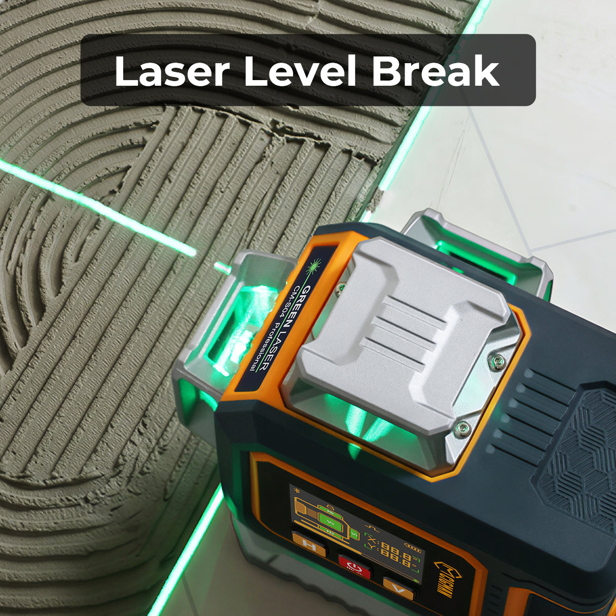
The current CIGMAN CM-701 page lists a 3×360-degree layout, leveling accuracy of ±1.5 mm at 5 m, a 4-degree ±1-degree compensation range, a 30 m line working distance, a 3.7 V 4000 mAh lithium battery, and an IP54 rating. Those are manufacturer-stated specifications. They describe the instrument, not the condition of your substrate.

CIGMAN CM-701 3×360-degree Laser Level
Three full planes help transfer a reference around a room. The page lists ±1.5 mm/5 m leveling accuracy, a 30 m line distance, a 4000 mAh battery, and IP54. Confirm the current specifications and manual before purchase.
- Choose a support point. Set the laser on a firm surface or a tripod position that will not be bumped while you take the readings. Keep the instrument high enough that the line reaches every marked area.
- Release the pendulum for a level reference. On the CM-701, the released position enables self-leveling. A continuously flashing beam means the tool is beyond its stated self-leveling range. Stop and correct the support instead of recording a flashing line.
- Use manual mode only for marks that do not need to be level. Locking the pendulum enables manual mode. Do not use that mode as the datum for a level floor or a level tile course.
- Decide whether you need pulse detection. The CM-701 page says pulse mode can be used with a laser receiver when the beam is hard to see. The receiver is not included, and the page does not name a universal pairing. Confirm compatibility with the current manual and receiver specification before ordering.
For a broader tool comparison, see our laser level buying guide. It explains why a 3×360 model, a cross-line model, and a rotary laser suit different jobs. Preparing the room around the right laser levels starts with the task, not the feature list.
Check Subfloor Flatness Against the Right Tolerance
For wood flooring, NWFA guidance describes the subfloor as flat, clean, dry, structurally sound, free of squeaks, and free of protruding fasteners. Identify the installation method before choosing a pass line. A wood number is not automatically a tile number.
| Installation condition | NWFA flatness example | How to use it |
|---|---|---|
| Mechanical fasteners 1-1/2 inches or longer | 1/4 inch in 10 feet or 3/16 inch in 6 feet | Compare the same span and reference length named in the project documents. |
| Glue-down or mechanical fasteners shorter than 1-1/2 inches | 3/16 inch in 10 feet or 1/8 inch in 6 feet | Use the stricter condition when that is the installation method you selected. |
| Concrete under wood flooring | Typically 1/8 to 3/16 inch in a 10-foot radius | NWFA says the wood-flooring manufacturer's specification controls. |
The table gives conditional NWFA examples, not a universal contract for every floor. For tile, read the current TCNA and ANSI material for the selected method and then check the tile manufacturer's substrate requirement. Large-format tile, uncoupling systems, membranes, and irregular patterns can change what the installer must verify.
- Mark a repeatable grid. Draw the room on paper and mark points that let your straightedge bridge the area being tested. Include transitions, doorways, perimeter zones, and any visible repair.
- Project one horizontal reference. Use the CM-701 horizontal plane or another level mode. Keep the support in place while you take the readings. The laser is your datum, not the flatness instrument.
- Measure beam to floor. At every point, measure from the same part of the beam to the substrate and write the result beside the sketch. Do not switch from floor to wall marks halfway through the scan.
- Find the total variation. Subtract the smallest reading from the largest reading. Compare that difference with the exact span and tolerance required for the flooring or tile system. Flag both the highest and lowest areas.
- Apply the tile documents when tile is the finish. TCNA material covers substrate requirements, joint sizes, patterns, and workmanship, but the public description does not give one number for every tile method. Do not borrow the wood table for tile.
Correct High and Low Spots Before Installation
When peaks or valleys exceed the applicable NWFA tolerance, the guidance directs installers to sand high spots and fill low spots with a leveling compound or another material approved for use under wood flooring. The repair product's technical sheet controls preparation, layer depth, mixing, and cure conditions. There is no single compound schedule that belongs in every room.
- Mark the repair zones. Circle high areas and low areas on the sketch. Keep the labels tied to the readings so you do not grind a valley or fill a peak by mistake.
- Remove high spots first. Sand or grind only as far as the approved method allows. Recheck the area before filling a low spot, because a missed peak can keep a patch from working as intended.
- Fill low spots with an approved material. Follow the selected product's surface preparation, water ratio, depth, and cure instructions. Do not substitute a fixed thickness or cure time from another product.
- Control dust during grinding. OSHA's silica rule applies to covered construction tasks and calls for the engineering controls, work practices, and respiratory protection specified for the task. Homeowners should also control dust and follow local requirements, the tool manual, and the repair-product instructions.
- Repeat the same scan. Return the laser to the marked support position, use the same points, and compare the new differences with the same installation requirement. A repair is not complete because the surface looks smoother.
Check the class and output information on the product label rather than guessing from beam color. FDA explains that higher laser classes have greater potential to cause serious injury if used improperly. Follow the label, manual, and local requirements for the exact tool.
Square the Room and Install From the Reference
After the substrate passes, start the layout from the room rather than assuming a wall is square. NWFA's layout guidance starts with a center chalk line and uses a second line at exactly 90 degrees. A laser makes the reference visible, while chalk keeps it available after the instrument is moved.
- Find the working center. Measure opposite walls, mark their midpoints, and snap a line between each pair. Where the lines cross is the starting point for a balanced layout. Check unusual alcoves separately instead of forcing them into the main rectangle.
- Build and check the perpendicular. Use the laser's cross-line or two-plane view to project the second line. Confirm the corner with a 3-4-5 construction or another dimensional check before snapping permanent chalk lines. The check tests the layout, not the tool's marketing specification.
- Transfer the reference. The CM-701's 3×360 layout can keep a horizontal plane visible around the room and vertical planes available for wall marks. Use only the line or plane you need so extra beams do not hide the working edge.
- Dry-lay the first runs. Place a row from the center toward each wall and inspect the edge cuts. Shift the starting line only after checking both sides. For hardwood and engineered flooring, mark the expansion space required by the flooring manufacturer.
- Preserve the marks before moving the laser. Mark two fixed wall points or snap chalk lines while the pendulum is in the documented self-leveling mode. If you must reposition the tool, align the new projection to both marks and recheck before continuing. Manual mode is for a deliberate non-level mark, not for restoring a level datum.
- Use the laser as an alignment reference while installing. Keep board ends, tile edges, and joint lines on the chalk layout. Check each installed area with the straightedge and the material manufacturer's method. A laser line does not establish a universal lippage limit or replace the checks for mortar coverage, joints, expansion, or movement.
For another interior transfer task, read how to use a laser level for ceiling work. For outdoor layout, see the deck-post guide or the ground-leveling guide. Each guide keeps the reference step separate from the surface-specific pass test.
Frequently Asked Questions
Can a laser level tell me whether a floor is flat?
No. It gives you a repeatable level reference. Use a straightedge or the test named by your flooring or tile documents to measure local peaks and valleys, then compare the result with that system's requirement.
Should I use a 360-degree line or cross-line mode for flooring?
Use the mode that leaves the reference visible where you are working. A 3×360 model can project a horizontal plane around the room, while a cross-line mode may be enough for one wall or one starting corner. The extra plane does not change the substrate requirement.
What does a flashing beam mean on the CM-701?
On the CM-701 page, continuous flashing indicates that the tool is beyond its stated self-leveling range. Set it on a steadier support or correct the angle. Do not record a flashing line as a level reading. Locking the pendulum switches to manual mode, which is a different use.
Can a laser level replace a chalk line for tile layout?
No. The laser helps you establish and check the reference. Chalk lines preserve that reference while you move the tool or spread adhesive. Use both, then check the tile pattern and edge cuts before setting material.
Is the CM-701 accuracy a guarantee that my substrate passes?
No. The listed ±1.5 mm at 5 m is a manufacturer specification for the instrument. Your substrate still has to meet the flooring, tile, underlayment, adhesive, and project requirements. Measure the surface independently and keep the documents for the selected system beside the readings.
References
- [1] National Wood Flooring Association, "Installation Guidelines," National Wood Flooring Association. Open the current source page. Verified August 31, 2026.
- [2] Tile Council of North America, "2026 TCNA Handbook for Ceramic, Glass, and Stone Tile Installation," Tile Council of North America. Open the current source page. Verified August 31, 2026.
- [3] Tile Council of North America, "ANSI A108, A118, A136.1 American National Specifications for the Installation of Ceramic Tile," Tile Council of North America. Open the current source page. Verified August 31, 2026.
- [4] Occupational Safety and Health Administration, "1926.54 Nonionizing Radiation," United States Department of Labor. Open the regulation. Verified August 31, 2026.
- [5] Occupational Safety and Health Administration, "1926.1153 Respirable Crystalline Silica," United States Department of Labor. Open the regulation. Verified August 31, 2026.
- [6] U.S. Food and Drug Administration, "Laser Products and Instruments," U.S. Food and Drug Administration. Open the laser-products guidance. Verified August 31, 2026.
- [7] CIGMAN, "CM-701 3x360-degree Laser Level," CIGMAN. Open the current product page. Verified August 31, 2026.
Get Professional Accuracy on Every Project
The CIGMAN CM-701 3x360° Laser Level for $149.99 offers 3x360° green beam (1h + 2v), 100ft range.
Shop CM-701 for $149.99 →



Leave a comment
This site is protected by hCaptcha and the hCaptcha Privacy Policy and Terms of Service apply.