


Recessed Lighting Layout: Use a Laser Level for Can Lights
A recessed lighting layout goes wrong in a very specific way: the centers are measured carefully, yet the finished row seems to lean toward one wall. Run the job as four checks in the room, not as one measurement on paper. Plan two different measurements, throw one straight laser line across the ceiling, square that line to the wall you chose, and inspect the cavity above each mark before anyone cuts. This sequence is for lights on a flat ceiling.
Keep the word can lights in mind as you plan. The laser does not decide how many fixtures the room needs, how much light each fixture should provide, or what a particular housing requires above the ceiling. It only gives you a repeatable line and, on a three-plane model, a repeatable cross line.

Plan the layout before you turn on the laser
Put these on the floor before the laser comes on: a room sketch, tape measure, sharp pencil, painter's tape, the fixture cutout template, a stud finder, and the CM-701 with a tripod or pole mount. If a tool is missing, stop here. Guessing an offset later is how a straight row still looks crooked.

Choose the reference wall
Draw the reference wall, the opposite wall, doors, cabinets, beams, and the area that must be lit. Choose the wall that people will read as the main visual edge. All of the row-to-wall measurements should come from that one wall. Measuring one end from the north wall and the other end from the east wall can produce a line that is mathematically straight but visually angled.
Set the end offsets and interval
Write two different numbers on the sketch. They answer different questions.
The row offset is the distance from the reference wall to the whole row. It must be the same at both ends later, or the row will look angled even if the centers are equally spaced.
The end offsets are the distances from the end walls, a cabinet run, or another stop to the first and last centers. Those two numbers place the lights along the run. They do not replace the row offset.
The clear run is the distance between the first and last centers, not the full wall-to-wall length of the room. Once that run and the fixture count are approved, divide the clear run by the number of gaps between centers. A 16-foot clear run with five centers has four gaps, so the arithmetic is 16 / 4 = 4 feet. If you start from a 20-foot room and forget to subtract the two end offsets, the row will not fit the walls you meant to respect.
Many first sketches start near half the ceiling height between centers. That is only a planning hint. Replace it with the fixture maker's instructions, the housing size, and what the room actually needs to light. If either end offset changes, erase the interval and recalculate. Do not slide one mark by eye to make the math look nicer.
Press a small piece of painter's tape at each end of the planned row, even before the laser is on. Those two control points are what you will shoot the beam through. If the tripod gets bumped later, you recover from these two marks, not from memory.

Set a line that is straight and squared up
For a row of cans on a flat drywall ceiling, the useful line is the one a vertical plane throws across that ceiling. A 3 x 360 unit also has a horizontal plane, but that plane is a level line at the height of the tool. It hits the walls. It does not draw the can-light row on the ceiling.
Straight and squared up describe different results. Straight means the centers share one line. Squared up means that line runs parallel to the wall you chose as the visual reference. A tape measure can give you equal distances from a crooked wall and still create a row that looks wrong. Solve the two geometry questions separately.
1. Set the mount
Stand where you can see both tape marks without parking the tripod in the ladder path. Set the CM-701 on the mount while the unit is still off. Tighten the head, then note a nearby fixed reference such as a door jamb so you can tell if the stand moved.
Check the transport lock before you power on. A self-leveling unit may flash when the lock is engaged or the base is outside its leveling range. Follow the symbols on the unit and its manual rather than guessing from the beam. Turn on one vertical plane and walk that ceiling line onto the two control tapes. You are not trying to make the ceiling itself level. You are choosing a visible reference that crosses both marks.
2. Square the line to the wall
The same vertical plane also hits the floor and the walls. Walk to the near end, hold the tape from that vertical line to the same baseboard or wall feature you used on the sketch, and write the number. Walk to the far end and repeat on the same feature, not on sloped trim. Rotate the mount until the two readings agree. Those two numbers are the row offset, not the end offsets along the run.
3. Mark the beam center
Mark the two end centers first. Press a scrap of painter's tape over the glow on the drywall. Put the pencil point in the bright center of the beam, not in the fuzzy edge. Then stretch the tape measure along the laser line and add the intermediate centers at the interval you already wrote down. If the tape sags, you are adding a second angle. Keep it in the plane of the beam.


Step away from the tripod, wait for the beam to settle, and repeat the two-end check. Touching a leg or leaning a ladder against the stand invalidates the numbers. If they disagree after any contact, start this check again.
Every center must sit on the same laser line, and the distance from that line to the chosen wall must be the same at both ends. If either test fails, do not mark the intermediate centers.
An old room may have walls that are not parallel. That is a visual choice, not a tool failure. You can make the row parallel to the main wall, center it between two walls, or align it with cabinets. Write down which choice you made. The laser can hold that choice across the room, but it cannot decide which sightline will look right.
Mark spacing and check the ceiling
Confirm the interval with the tape
The CM-701 listing gives an accuracy of plus or minus 3 mm at 10 m. That specification describes the tool's stated leveling performance under its stated conditions. It is not permission to skip a visual check or a cavity check. Use the beam as a guide, then confirm the end gaps and the center-to-center measurements with your tape.
Leave marks provisional
Use the actual light housing or its supplied cutout template when you check clearances. A center can be perfectly placed on the laser and still fail because the housing hits a joist or leaves too little room for its required components. Mark a proposed center with tape, then compare the template with the framing and the manufacturer's instructions. Leave the mark provisional until that check is complete.
Put a small X at each accepted center and write the interval beside the first mark. Do not draw a large circle until the center has passed the framing, duct, pipe, wiring, and housing-clearance checks. Measure from the beam to the surface at each proposed center. A crown can make a beam appear to change height even though the reference is unchanged. If one spot is high or low, record that condition and follow the fixture instructions rather than bending the row to the surface.
Sight the row before you cut
Stand at the first tape mark and sight down the row the way you will see it from the doorway. Then walk to the far end and do the same. The centers should read as one line, and the two end gaps should look alike. If they do not, erase the mark and reset the line while the ceiling is still intact.

A test opening is still a cut. Isolate the circuit that could serve the area, verify the absence of power with an appropriate tester, and follow local requirements. If you are not qualified to perform that work, stop at the pencil marks and bring in a licensed electrician.
Fix visibility and setup problems
Ceiling work often fails because the operator cannot see the line well enough to mark its center. Treat a faint or unstable line as a setup issue, not as an invitation to estimate.
Daylight washes out the line. Close blinds, shade the target, or work when the room is dimmer. If you still cannot identify the center of the beam, postpone the mark and follow the product label and manual. The tape trick in step 3 is the same fix: give the glow a darker edge, then mark the bright center.
If the beam is flashing, turn the unit off, check the transport lock, and move the base to a firmer support. Wait for the ready indication described in the manual. A flashing warning can mean the unit is still settling or outside its self-leveling range.
If the beam stops at a cabinet or bulkhead, mark the visible section, record a control point, and move the unit only after locking it. Re-level it at the new position and pass the beam through the control point. Do not blend two slightly different lines.
If the line looks thick, mark its center consistently. If the glow is too broad to judge, reduce ambient light or use a target card. A thicker glow is not a reason to widen every cutout.
For more detail on choosing a beam color for indoor work, see our article on red versus green laser level visibility. For a broader ceiling setup, use the laser level for ceiling work guide. Those pages cover visibility and mounting choices; the acceptance tests in this article still control your can-light marks.
Why the CM-701 fits this layout
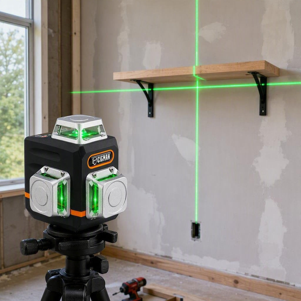
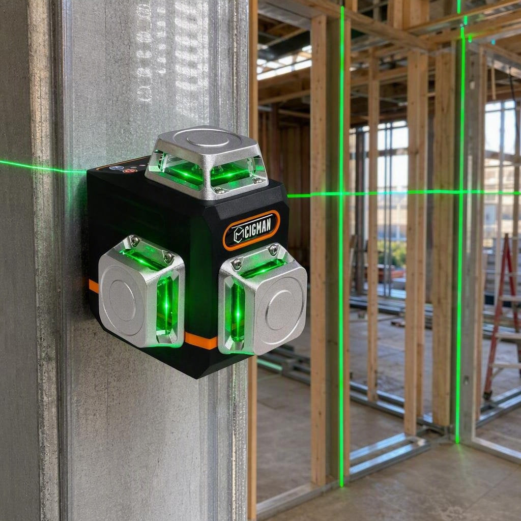
The CIGMAN CM-701 is listed with a 3 x 360 degree green beam: one horizontal plane and two vertical planes, with a 100 ft range. For this layout, one vertical plane throws the row across the ceiling. The second vertical plane gives a 90-degree cross if you need a grid. The horizontal plane is a level line at the height of the tool. It is a match for wall-height work and drop-ceiling height, not for drawing the can-light row on a flat drywall ceiling.
The same product record lists self-leveling within plus or minus 4 degrees and accuracy of plus or minus 3 mm at 10 m. These are product specifications, not a guarantee that a ceiling is flat or that a row will look balanced from every viewpoint. Mount the unit firmly, wait for the ready indication, and repeat the end-gap check after any move.
The model is a tool choice, not the layout decision. A two-line level can still mark a straight row if you verify parallel with separate measurements. Choose the three-plane CM-701 when keeping a ceiling line and a wall check visible saves repositioning, then use the same marks and checks whether you work alone or with a helper.

CIGMAN CM-701 3x360° Laser Level
- 3x360° green beam (1H + 2V), 100ft range.
- Self-leveling ±4°, accuracy ±3mm/10m.
- Remote control, USB-C rechargeable.
Frequently Asked Questions
How far apart should recessed lights be?
There is no single interval that fits every room, fixture, ceiling height, or lighting plan. Write a row offset from the reference wall, then place the first and last centers with end offsets. Divide the clear run between those two centers by the number of gaps. Five centers create four gaps. A first sketch near half the ceiling height is only a planning hint. Replace it with the fixture instructions before you cut.
Do I need a three-plane laser for can lights?
Not for every small room. A two-line unit can hold a straight ceiling row if you make a separate parallel measurement. On a 3 x 360 unit, one vertical plane draws the row across a flat ceiling. The second vertical plane gives a 90-degree cross. The horizontal plane is a level line at the height of the tool, not the can-light row.
What should I do if I cannot see the beam on white drywall?
Dim the room, shade the target, and use painter's tape or a target card to give the beam a darker edge. Look for the center of the glow from a stable position. If the line is still uncertain, do not mark it. Follow the model label and manual for exposure limits and use a compatible detector only when the manufacturer lists that combination.
Can I cut the ceiling as soon as the laser marks are complete?
No. The marks are ready only after the cavity above each center is understood, the relevant circuit has been isolated and checked by a qualified person, and the housing clearance is confirmed. If any of those conditions is missing, leave the pencil marks in place and get the right trade help.
References
- [1] CIGMAN, "CM-701 3x360 Laser Level: Product Planes and Range," CIGMAN. Open the current product page. Verified August 31, 2026.
- [3] Occupational Safety and Health Administration, "29 CFR 1926.54 Nonionizing Radiation," United States Department of Labor. Open the regulation. Verified August 31, 2026.
- [4] Occupational Safety and Health Administration, "29 CFR 1926.416 General Requirements," United States Department of Labor. Open the regulation. Verified August 31, 2026.



Leave a comment
This site is protected by hCaptcha and the hCaptcha Privacy Policy and Terms of Service apply.